
This review is my opinion from 40 years in manufacturing and a life of tinkering with items from the mid 1800's to today's products.
If you want modern, simple reliable switches, the legacy Lionel O22 switch design and its variants may not be an answer. You can make them reliable in some cases, but the foot print for the switch motor is large compared to many offerings today. Ross even offers direct plugin tubular track switches with modern switch motors.
If you are interested in using these Lionel switches these notes may be for you.
Lionel has made 2 size of O tubular switches. O31 and O72 curves in various designs over the prewar and postwar years.
Fastrack switches 036 and O72, are not covered here. O27
tubular switches with O27 and O42 curves are not covered here. O27
is the nickname for the shorter tubular track made by Lionel for smaller
layouts and O27 wheeled trains.
O, O31 diameter curve switches
O, O72 diameter Curve
Switch Controllers at the end.
Many parts for the modern 6-5132/3, 6-14062/3 and 6-65165/6 switch are listed on Lionel support page. Many are interchangeable, even with the O22 switches. No parts available for the 6-23010/1 switches.
Switch reviews
Maintaining the O22 remote control switches is a simple process with many areas or steps to check. You are fighting corrosion, wear and design changes. The basic things you need to "fix" are cleaning dirty areas, loose track attachments, corroded or worn connections, corroded or worn contacts, some wiring, rust and replacing old lubrication in key areas.
This Classic Toy Trains O22 Switch discussion has many suggestions for fixing and maintaining these switches. More pictures would be helpful, I have many here.
This OGR discussion also adds information.
These switches were made over many years. Some screws changed, lantern holders went from metal to plastic and more. Make sure you don't loose the screws on a O22 switch, it may not be easy to find replacements.
Basics of the O22 switch and motor
There are 2 coils in the motor. One or the other is energized to move the switch one way or the other. Both coils have Center rail or Power available all the time. The switch actually "grounds" the coil to cause the coil to energize. The train wheels "ground" the non-derailing outer rail to cause the switch to activate for the non derailing feature.
When you take the cover off the motor (2 screws on the back) and remove the switch motor from the switch, (2 Screws on the back and one captive nut to not loose!), this is what you see.
This one has had an LED and resistor added to replace the light bulb. You can clearly see the fixed voltage connection. I would strongly suggest this be used with a constant 18-19V for these switches. Track power may be too low at times to reliably run the switch. The white grease in this picture shows the slide areas you need grease, but this one is overdone in my opinion.
Grease goes on the lantern gear and the black base piece that slides on the bottom plate where dimpled and on either side under the light socket. Most of the backside of the black piece is in the air. Grease and oil also collect dirt, use sparingly and only where needed.
The copper color Lock Hinge that "locks" the switch in place. There is can be adjust, and is explained in the O22 modern switch below.
The other end of the switch motor. The motor can be mounted right or left. There are extra contacts to support the motor being mounted either way.
There are 2 center rail contacts, but only 1 is used at a time. The fixed voltage plug when used disables the center rail feed to the coils. On these postwar switches, the center rail contact is wide, almost to the outer edge of the motor housing.
2 outer rail or ground contacts, 1 used at a time.
2 non derailing contacts that are diagonally apposed, both are used no matter the position.
The sliding contact is 2 sets of switches. One for each coil. Grounded by the switch or the train touching the non-derailing track segment. Once the switch is thrown, straight for example, the straight sliding switch at the end of the movement has the lock drop in place and the straight switch is no longer in contact. This keeps the coil from being constantly active when the train is running through the switch. When turn is thrown, at the end of the throw the lock drops in and the contacts are off the switch and the turn coil is disabled.

The 2 control switch light bulbs are always connected to the switch and non-derailing side of the sliding switch. The light bulb draws a lower current, not enough to energize the coil. LED lights even less. So when the Green bulb is active in the control switch, it is telling you the turn is connected in the sliding switch and ready to throw. Once the turn is thrown, the sliding switch dis-connects the turn side and the Green light goes out. Now the straight side is connected and the Red light is on. You may have the bulbs set opposite, depending on your taste. Another reason that once thrown, the sliding contact disconnects the current flow from the coil, so only 1 light bulb is lit in the controller.
I had trouble with the switch motor shown above. It had continuity problems in the sliding switch. This model, postwar 1950 and newer, has very little contact material under the contact ends. These switches have the bayonet light bulbs.
Another way to tell if there are sliding switch contact problems is the bulbs in the controller. If they are good and in the socket well, one or the other should be lit. If one doesn't lite or is intermittent, then the sliding switch may have contact problems.
If the switch is sluggish or non-operational 90% of the time it relates to the contacts on the sliding switch. My maintenance steps after removing the cover and the motor from the track.
I had to bend the sliding switch contacts and add a lot of tension to get the contacts working reliably on one postwar O22. One side was still sluggish. I changed out the 711-216 switch plate, with a 711-170, 1950 and earlier. I find these easier to adjust, but both can work well. Modern switches also use 711-170. New 711-65 rivets are needed. Many Lionel parts suppliers still have the rivets and parts for these switches.
711-216 slide plate from the contact side

711-170 slide plate from the contact side. Showing the taller contact material under the switch bar. This one needed minor adjustment after cleaning up the contact areas. Also see late prewar/early postwar motor near the end.

Check the light bulb wiring and with the bayonet bulbs, check the spring. A rusty or collapsed spring will make the bayonet bulb contact bad. When replacing the bulb wiring, be careful to route the wire through the hole in the bottom and out through the right in the picture below. Then on the wire guide. All this is there to assure it doesn't get caught in the lantern and slide mechanism.

The cast metal lantern housing on the older switch motor had been bent and it interfered with the cover when the switch was thrown. I used needle nose pliers to hold it near the base, above the gears. Then constant pressure for 20-30 seconds. It bent enough to clear. This kind of metal breaks easily if you try to bend it fast. It may still break if you bend it slow. Be ready to replace it if you need to bend it. Newer models use a plastic housing that doesn't tend to stay bent.
Now look at the switch and the contact areas it has that connect with the switch motor contacts. These need to be clean. Also there is one "paper" insulator that is needed also. This was missing on this switch. I used card stock from a greeting card to make the insulator. I cut T slits on both ends. Then carefully guided the tabbed ends created by the T slits under the contact bar to hold it in place.
`
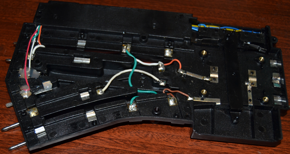
Looking at the complete switch with the cover off. Over time the connections and tabs used varied, but the basic function is the same. The No Touch area is where the non derailing connection crosses and outside rail. If the rail tab has bent up it may touch and needs to be bent down. Use thick paper as an insulator if needed. Make sure all rail tabs are tight and in place. Soldering all the crimped connections can assure a good electrical contact. There is also a ground/outer rail wire that connects the turn outer rail connectors. It also connects the flat outer rail connection. Make sure it will not short across the non-derailing lead.

This is another version of the postwar O22 In some cases the outer rail tab that is bent over is missing and cannot touch. This appears to be intentional. The rail is held in 3 other places, so not a problem. This also shows the crimp connections soldered. I clean the area to solder, a little electrical friendly flux and a small amount of solder. A big glob is not needed. Just enough to assure good electrical connection. cleanup any excess flux, even the flux from the original manufacturing if evident. You can see the brown flux blobs below.

Adding insulators under and over the Non-derailing leads. The top one is folded to protect both sides. Some may consider this extreme, but I will never have to worry about a "short in the switch". I find old greeting cards just right for this.

A close view of the flat outer rail. Some say it isn't always hooked up to be functional, but all the switches I have seen have it connected to outer rail/ground. Is it absolutely needed? Not with inner/outer wheels both able to contact. This would contact the flange on the wheel in the gap areas. Probably for added common connection reliability. For some prewar and early post war engines with taller flanges this is where the flanges contact vs. the wheel face on the outside rail also. Maybe this was to help those older wheels make contact. Make sure you polish this up also.

A paper insulator was also used under the metal cover plate. It was not always used or often left out. It assured no shorting of the inner rail connections or non derailing connections if there were point pressure bending the cover in. It may be wise to use a paper insulator after soldering the crimped contact areas, to assure there is no shorting. This is the original


I switched out the bulbs in the switch motor and control switch for an LED bulbs. All three incandescent bulbs were 18v .1 Amp. 5.4 Watts for all 3. Traditional incandescent bulbs soon add up to a lot of power. LED light bulbs prevent melting the lantern covers. Also the old style switches with the bulb exposed do get hot.
The bayonet style bulbs work the best for remaining tight in the socket. The screw in bulbs may come loose over time.
I modify the fixed voltage plug for better contact and reliability. I cut the shoulder off so it would push in all the way. With the shoulder it only went on the pin 1/3 of the way and didn't feel secure. Taking off the cover and pushing it on all the way, the cover would not go back on with the shoulder there, almost but not enough. Then I cut a small groove with a file where the spring contact arm is. Now when inserted the spring acts as a catch. Now it should not work off the pin as the train goes by time after time. Careful, cut the groove too deep and you will get to the metal and then your track will have constant high voltage! A little No-Ox-Id on the pin helps the contact also.

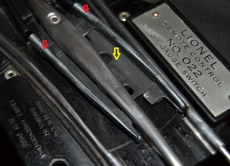
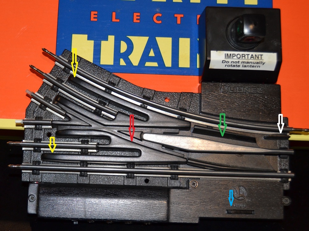
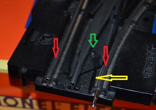
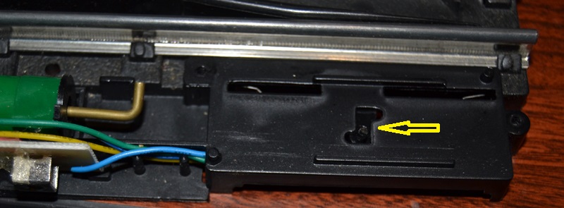
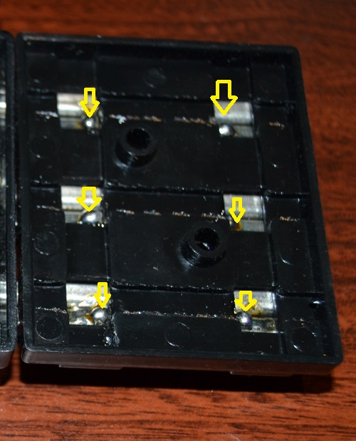
With the O22 the frog is not grounded. The frog has metal elements, red arrows. These are attached to an insulated plastic or fiber board, yellow arrow. Both metal sides of the frog are electrically isolated from each other. This is so it wont short the center pickup when one side of the frog or the other is close to the center rail. The metal piece may ground against the outside rail, but I wouldn't count on it. Just note you are only guaranteed ground on one rail going through the switch. On the other outside rail there is a grounding gap of 4.5"/115 mm straight and a 3"/75mm gap turning. If traction tires are involved, on an engine and it stops in a switch. check all other wheels are grounding well on the engine.
I checked a new in the box 6-65165/65166 O72 right and left hand switches. These are labeled made in China. Also O31 curve 6-5132 and 6-5133 switches. Point of manufacture not labeled, but maybe USA since the Lionel, Mount Clemens Michigan name is embossed in the switch. While the O72 just have Lionel LLC. The O72 switches both switched well out of the box. The O22 did not. Both were shelf queens, but unused and unopened.
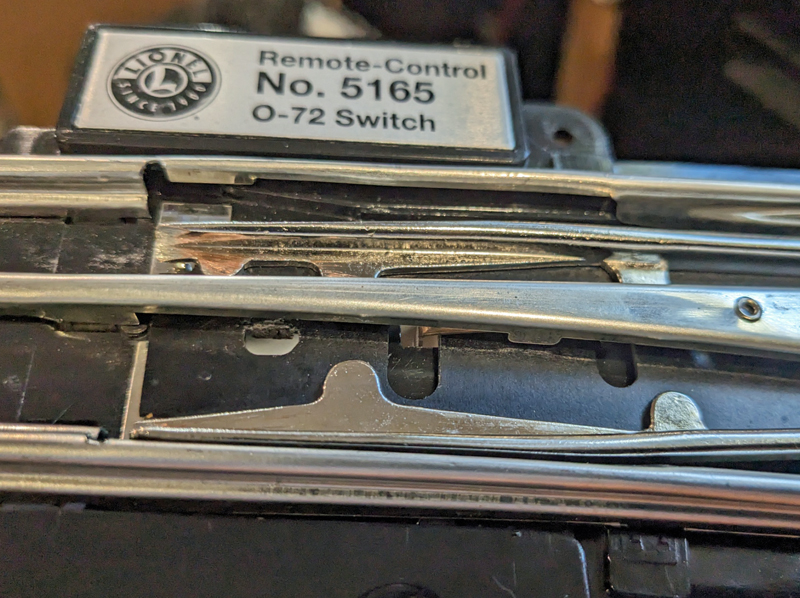
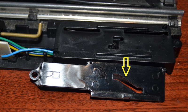
One thing I have found is some heavy engines may not work well through these modern switches. Why? Look at the notch cut in the track for the turnout switch. The notch cut is deep and wide. I found during assembly if the pin took too much force this part of the track could buckle. With a little pressure it moves. I had a 783 4-6-4 semi scale loco that would jump and derail the rear wheels going through these switches. I think the track cut and a little spreading at just the right time caused the engine to drop and then jump back up as it proceeded along. Causing the derailments. Maybe you could fix it by putting a shim between the name plate area and this part of the track to hold it from flexing out. I dropped in some Preway 711 switches and fixed the problem.
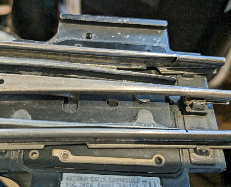
This shows the same area in a prewar 711 switch. The notch is small and short. The rail will not flex. No problems with jumping and derailing on this switch. even 80+ years old it still works. I did use Postwar switch motors with it.
For the O72 switch all the connection joints are now soldered or are wires that are soldered. For the O72 were there just wires where there are plates in the O22 switches for the outer rail and center rail connections. This follows the traditional prewar 072 switches.

The modern O22 is similar to the postwar switch layout with metal runners with crimped ends. Where the top non-derailing lead crosses the outer rail tabs, there is only 1 tab, not 2 as discussed above. No chance of shorting there. . The other places where they cross over rail tabs, they have insulating pads. These modern switches still have the flat outside rail contact electrically active. Only the flange will touch it.

I cleaned, fluxed and soldered each crimp area. Just a little bit of solder to get a connection. Not a large blob. These modern switches are thermoplastic and too much solder heat is a problem. Then I washed the excess flux off.


The O72 sliding switch has the taller contacts and liberal contact grease on the 4 pads. The motor side non-derailing contacts are a circuit board that cannot be bent up. But the contacts on the track side are spring loaded. I added No-Ox-ID to the main ground strap and the 2 non-derailing contacts. Much lighter than the amount Lionel used. Too much can interfere eventually.
The one thing I had to do was bend the center rail spring contact so it was centered in the contact area on the motor. It was at an angle and on the edge of the contact strip. I didn't want it loosing contact in use. Just check and make sure it is on the contact pad well. The center rail contact pad is not as wide as the O22.

The O22 sliding switch had the tall standoffs, but no contact grease. Also it was the postwar style were you bend up the 2 edges to increase contact pressure for the non-derailing contacts if needed. There was light corrosion on the switch contacts. The backing metal for the switch felt to me like a lighter gauge or not as well tempered metal. It works. There is also no grease on the gear or sliding area of the switch around the lantern area.

I used a pencil eraser to clean the pads of corrosion. It worked, but sluggish. I added a double, step bend at the ends of the contacts to add pressure and keep the contacts flat. A light coating of No-Ox-Id contact grease and the switch motor was working well.

Concern on mechanical design and quality The O72 Right hand switch when set to straight, held nicely, but in the turn position it can easily gap enough to derail. The slot for the driving pin has a lot of excess play. I measure the pins and the slots of the 2 switches. I also measured a postwar 022.
O72 Good on the left vs. Bad slot on the right. Good is oval, Bad one is not oval.


It looks like the right hand switch has a manufacturing defect, the slot was cut too wide. Quality isn't getting it past the inspector, it is making it as designed! I made a shim to tighten up the slot .030"/1.5mm on the bad turn position side of the slot. If I had bought these new, it would go back for replacement. They have been on a shelf for a few years.
This is a pair of my 3D printed L shaped shims with skirts. They are so small, without the skirts they would not stick and would fail. Skirt is cut off later. They worked with a .4 nozzle, but a .2 would be better. Shim is super-glued on.
![]()
Locking Hinge Adjustment, this is where we can adjust out some of the slop from manufacturing tolerances
There is a joggle in the locking hinge when looking at some of the switch motors. One side contacts the locking hinge for the turn position, the other side contacts the lock hinge in the straight position. This means by careful bending of the locking hinge one side or the other, you can adjust the "slop" in the turnout in the locked position. There was a design change in the early prewar switches to enable this adjustment.
Adjusting the locking hinge as needed takes some practice. This is the O22 with the noticeable joggle. In this position the bottom tab is contacting the hinge, but the top is not. Once thrown to the other position the top will contact the hinge, but the bottom will not. It works to keep the switched track against the rails both ways. This Locking Hinge adjustment should be done with the switch attached to the motor.
On the modern 5165/6 switch motors I found this locking hinge very hard to bend. They use a different metal than the postwar hinges. It acts more like a spring and does not bend easily. I replaced then with postwar versions when bending for adjustment is needed.

Light Bulbs
The O22 screw in light bulb is the traditional design. One was just sitting in the housing. It had not been screwed in. In other O22 modern switches with the screw in bulb, I found the factory had used a glue on the top of the bulb threads to keep the bulb from loosening. I had to use needle nose pliers on the metal base that was exposed to get it out. The remnants of the glue were noticeable on the top thread.
The Modern power tap post is now a split post. Pushing the Fixed Voltage plug on the post for the O22 was a press fit. A little contact grease was needed. If the split post is bent in, together, it may be too loose. The split allows you to use a small straight blade screw drive to adjust the diameter bigger if needed. Careful, they don't survive many adjustments.
Warning about the light bulb in the O72 switch This switch does not have the standard "bottom" in the light bulb base. Usually with bayonet bulbs there is a non powered spring with the power contact and insulator on top of the spring. For the O22 there was a 2nd insulator under the power contact in the bulb base. The power wire going through the spring. On this design no bottom insulator. The spring is powered and relatively large and no insulator protecting it. DO NOT CHANGE BULBS WITH POWER ON. Reports are the bulb power spring easily causes a short. The wiring is thin and it caused the power wire to melt off the insulation or break. In this case wire was not heavy enough to draw enough current to cause the transformer circuit breaker to trip. The switch motor had to have wires replaced to work again.
Wiring, Materials and Final notes on modern 072 switches
I do not recommend using the modern O72 switches.
Some have also voiced concerns about the gauge of the wires in the new switches. The O72 and O22 are similar gauge wires. I am not about to destructively test a postwar and modern switch motor to see if they can survive a direct short before a ZW 275 breaker trips. If you want, a fixed voltage plug with an inline fuse may be the best to protect the switch. How big a fuse? Incandescent vs LED bulbs and the switch power combined, maybe 1 or 2 amps?
The older switches were Bakelite, a thermosetting plastic. Stable material with good wear and resistant to heat and solvents. Heat from soldering usually had little effect.
These new ones are thermoplastic and soldering heat can melt them. Be careful with heat and any track cleaning fluids. Bright sun or heat may warp them. Since the wear properties are not as good, I believe this is the reason a metal slide plate under the one end of the switch was added to the modern O72 switch, but not the O22. Both old and new have the sliding tabs under the switch, with Bakelite an extra sliding surface was not needed.

It seems to me the postwar switch has a little more of a chisel point on the ends of the switching track where the train enters the switch. That may be from wear. A little careful filing can add it to the modern switches if needed. This may help with steam engines front trucks that don't have enough pressure. They tend to rise up when the flange is dead against the rail and catches in the switch if there is any gap. When riding normally, the wheel is centered and the flange is not a problem.
Vertical slop at the pivot area of the frog seems to be to be .010-.020" more than the postwar O22. Is it a problem, Yes, the frog can tilt as a result.
The O72 backing plate did not have the hole to match the hole in the switch on the end. Traditionally a screw down hole. The one between the straight and curved end of the switch. Neither is the hole re-enforced to take a screw to hold it down. It would tend to crack if a hold down screw was used. May want to tape over the hole to keep dirt and insects out. All 3 Screw down holes on the O22 were re-enforced and had a hole through the backing plate.
Are the metal rails the same specification steel as the postwar switches? That would take a lab to determine. As noted above they are not as strong as the prewar 711. There are notable areas of weakness at the frog.
Prewar 711 O72 switches, early
version. Recommended after updating Non-derailing as
noted below and using a postwar switch motor.
Prewar 731 switches are similar to the later 711 switches. They use the T rail track, not the tubular rail.
The prewar 711 O72 switches have the following differences compared to the postwar O22, or modern O72. They are 82+ years old and may need help.
The following pictures show what to look for in 82+ year old switches.
First look for Zinc pest, is the metal sound.
The rails may be knocked out of position and bent. You may need to fix bends, rail ends, rail position and corrosion problems to make them useful. Make sure the non-derailing crossover is tight at the rivets.

The rails that activate the non-derailing feature are insulated and closer to the switch. In this case another rail has been knocked out of position. This is an insulated rail. Be careful you don't knock the insulation out of the rail when you move it back.
The problem with this non-derailer design is the center pickups cross the ACTIVE non-derailing contact rail. This can trigger the switch when not desired causing a de-railment.
If there is only one pickup on a car, it may act like a ground and throw the switch. The same will happen when one of the 2 pickups on an engine does not make good contact. Also if using a postwar switch motor and using the power tap for constant voltage, running the engine slow in conventional mode will have a large voltage difference and it may throw the switch causing a de-rail. I have seen this from personal experience with these switches in use.
What I suggest is to disconnect the wires from these non-derailing pickups and leave the rails insulated and inert similar to postwar switches. Then add 2 tracks, each with an outer insulated rail after the curve/straight side of the switch. The insulated rails will need insulation pins on both ends to function correctly. Then a wire from the insulated track to to the corresponding left or right post on the switch motor. You now have a more up to date non-derailing contact where the center pickup never crosses the non-derailing rail to cause problems.
The rail pins are in the ends of the rails to help shorten the center rail gap when going through the switch. The non-derailing rails are NOT connected to the outside rails. The center pickups will roll over these rails. On later 711 and postwar switches these rails are plastic/bakelight and not electrically active, to prevent the false activation of non-derailing as listed above.

This shows the other end of the 2 rails that have been knocked out of alignment. This switch uses standard rail ties to hold the ends of the 2 track sections.

The other side of the switch, where the motor mounts. There is a hollow section in the casting that is filled with an insulated insert. Similar to postwar and modern.

More of the backside wiring. In this case the center rail continuity wires were all gone and had to be replaced.

The prewar motor is similar to the postwar for the sliding switch, but the locking mechanism is a different. In this case, the board was broken.

In this example, the board is intact, but there is not a good way to adjust for both locking directions independently.

Later Prewar, very early postwar switch motor.
I found this variant of the slider switch in one postwar switch motor. My estimate is this is a very early model of the postwar O22 motor. It looks like this is a carry over from the prewar, 711 later model switch motor. For the Prewar 711, the 1 mounting holes were bigger. It has a voltage tap added. The switch contacts were originally designed to stand taller for this design, they went through the sliding switch board that had 4 ears. There is one problem with this design. The Locking Hinge will only adjust the centering of switch. It touches the rivet head in the middle, the same area of the hinge for either position. It will not allow adjusting both positions as the later design with 2 contact points on either end. The only way to adjust this switch is to adjust for 1 side by bending the bar and then use solder, or something similar, added to the other side of the lock hinge bar to get the adjustment needed.
This motor also had the end of the shaft sealed, probably to keep dirt out, but may have caused air resistance on one direction.


711 considerations
The insulated rails need to be checked to assure they are not shorting. What do you do if you have to replace the insulation paper and don't want to bend the tabs? Remove the paper, usually bit by bit. Then use pieces of toothpicks to hold the track centered in the tabs and off the plate. Then use liquid tape type of products. Brush on as liquid and let harden to hold and insulate the rail.
After cleaning the corrosion on the contact areas of the rails, re-forming the rail ends, re-soldering and replacing some of the missing wiring in these prewar switches they can be usable. Over time some of the rails have been dinged and bent. It is not easy to remove dings in the top of the rails.
The outside straight rail that runs the length of the switch on both prewar switches will move within the locking tabs with a little tapping, Not good, you want them to stay aligned correctly. As shown in the picture above, some of the other rails slid in their mounts. Tightening the cast tabs that hold the rail doesn't work well. The postwar and modern switches have a different and probably better design for retaining the rails. Impossible for them to slide out of position.
Going fast through the switches could be a problem when relying on the non-derailing feature on the early prewar 711. The early prewar 711/O72 switch has about 1/2 the distance for triggering the non-derailing feature compared to the later prewar 711, postwar O22 or modern 072. This is why you need a postwar motor with the voltage tap run at 18v, to assure a speedy switch action. It will not be easy to insulate the end rails where they are held in the metal base if you want them to become the non-derailing switch similar to the Late Prewar 711 or modern O72.
Summary of 711 switches
I do not recommend using the early prewar switch motors. Part availability, no dual side adjustment and lack of a voltage taps are the main problems. I would suggest using a Postwar motor on these prewar 711 switches. You will have to drill out the 2 screw holes on the postwar switch motor to work with the larger mounting screws for the prewar 711 switches.
The prewar 711 switches survived and can still be made usable. That is amazing. I do not see them as the "best" switch design since there are non-derailing problems. Later on Lionel changed some of the design elements for good reasons. If you like them or want an all prewar track, good.
I was able to use fix these 711 switches. I added Postwar switch motors and they work well in my layout. I am using 14v to power the switch motors.
Modern 2 O31 switches 23010/23011
A different design
I do not recommend using these switches.
These switches were made for about 5 years and then discontinued. They show made in China. The traditional style was re-introduced a few years later. They were designed to reduce the area needed for the layout. It appears to me they were made to fix some of the problems of the past, but not considering what was "good" in the old design. A problem with new "versions" I have often seen.
What changed?
Overall the connections look good. All wires soldered. A small light bulb, hopefully no worries about melting the lantern.
The lantern plate with the cover off.
Notes and cautions with this switch.
Over time the micro switches should stay cleaner and trouble free in regular use. If there is ever corrosion on the switches, There is no way to clean them.
Don't turn the lantern. There is a large, ugly warning sticker on the switch telling you not to. it will break!
The mechanism locks well when in position for straight or turn.
Don't use track voltage. If it goes above 14V, you may harm the switch according to the documents. Run it from Accessory power set to 14v. Also if your layout is using a large transformer, you should put a fuse less than 8 amps in line with the accessory power to the switch. 2 amps would be fine in my estimation.
The center rail gap of 3.5-2.75" or 60-70mm is the same as the O22 post war switches. When going through the switch one outside rail is fully grounded. However the other outside rail is not for 6.5" or 165mm. For both Straight and turn. 2"/50mm more than the O22. If you have an O-4-0 or 0-6-0 engine with traction tires, both on 1 side, and no tether to the tender, you may have "ground" problems going through the switch since the ground straps in the center are no longer there. If engines stop in the switch, check for outer wheel or front/rear truck grounding problems.
The non-adjustable nature of this switch is the other area people may have trouble with this switch. Some report their engines don't track well through the switch. If the frog is not close enough to the rail when thrown, then the wheels may derail in the right circumstances. If there are problems and the frog does not fit tight in one direction or the other, the only suggestion I have is to carefully use a heat gun or soldering tip and some pliers to bend the end of the frog until it is against the track as it should be. To assure the wheel flanges do not get behind the frog.
After looking at the strength of the 2 main switch components, be careful. On an HO switch, no trouble, but an O system is 8 times the weight. Will it take your full size Hudson running through the track when the non-derailing fails and it hits the switch backwards? Yes, will it survive 50-1000 times over the years as the Postwar O22 have? maybe not.
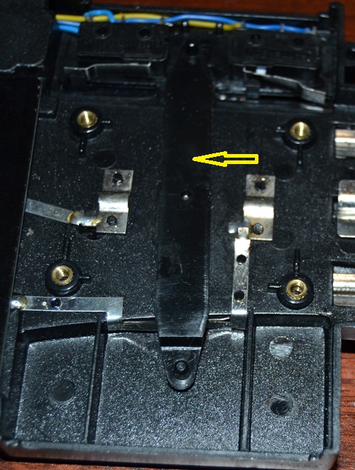
Switch bar from bottom of switch.
Then top of switch and drive dog on switch bar.
Top of mechanism that converts horizontal action to vertical.
The small track extensions had nothing in the design to hold the track in place. Solder bumps were added to hold the track.
23010/1 conclusions
It is smaller and can be more versatile, but I would not put it in a hard area to reach. The problem is no adjustment for the switch and possible durability of the switch mechanism overall. There may be a good reason when switches were made again later, this design was not re-used.
General ConclusionsThe postwar O22 switches are the standard for durability and toughness. They are 50-75 years old and some refurbishing should be done before being put in use.
With Prewar switches, use postwar motors when possible and modify the non-derailing option as needed.
What are the options for using the modern switches? Traditional designs look good, but check for manufacturing defects and proper adjustments. It is the quality of the product that matters. Then test for reliability. Modern 3rd party switches may be a better choice.
Non-Derailing rail is not consistentThe Non-derailing rail on the turn side of the O72 and 23010/1 switches is the opposite outside rail compared to the O22 switches. It works, just be careful during assembly.
Name plates
The name plates for the Prewar 711 are held on with bent tabs, Postwar O22 are riveted on, Modern O22 screwed on and on the O72 switches, glued on.
Coils
To test the coils, ground then directly at the solder connection to the coil. If they are still sluggish with no mechanical drag causing the sluggish response, the coils may need to be replaced.
Switch ControllersThe controller is a momentary contact, grounding switch. They are essentially the same switches for all controls. It grounds the Outer posts on the switch to the common or outer rail connections. The middle wire from the control goes to the center post on the switch or any ground/outer rail connection. This may allow you to use 2 wires to the switch and a 3rd to a common ground on your layout. Simplifying the wiring. This switch can be duplicated with modern components.
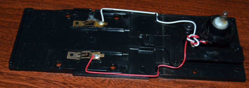
The picture below shows an early model switch with the cover removed. 2 screws in the bottom of the controller allow you to remove the top.
Often the wires need to be replaced after 30 or more years. The wires in the picture have hard, cracked insulation and need to be replaced. If you use the 3 wire cable as a replacement, the middle wire in the cable goes to the ground or outer rail connection.
The light bulbs are connected in parallel with the switch. Any time the slider switch in the track switch is connecting one side of the switch, the light bulb will have power. It is grounding the coil in the switch, but the light bulb doesn't pull enough current to throw the switch or cause too much heat in the coil. When replacing the bulbs, make sure they do not draw more current than the original 18v rated bulbs. Using modern LED bulbs will reduce the power draw for the lights and through the coil.
There are 2 major variants. This one shows the colored bulbs with no cover. Newer ones use smaller, clear bulbs with colored lenses in the control. I recommend LED bulbs on the older ones to assure little fingers don't get burned by the bulbs.
Common problems with this switch is a broken return spring or a broken contact. Make sure the contacts are clean and don't have a corrosion layer. When using the switch, teach young users to move the switch just enough to work. Continually moving to the "stops" puts stress and wear on the springs and the contacts.

The backside of the switch. The metal plate is the common ground or outer rail connection. The light bulbs and switch are connected to this plate.

By changing the outside wires at the switch you can change how the controller switches to turn vs. straight. The lantern cover can be installed in 90 degree increments so you can set red/green to show as you desire. Often Green for straight and red for turn.
As I find out more I will update.Back to Main page.
Last update ASept 8 2023