How do you get a postwar whistle to go from Sounding Like Rattling Marbles to Sounding Like a Whistle?
Here are some tips. Whistles are a simple electrical relay and motor. Time, wear, corrosion and over-oiling have taken their toll.
These old whistles need voltage, so if your train is creeping along or low throttle, don't count on it whistling. Beyond that, they need to be in good repair.
Cleanliness is whistle heaven. Along with spinning, not wobbling. Electric motors will wobble if there is too much play on the shaft or too much out of balance. Wobbling can cause it to rattle and reduce RPM. Which means no whistle.
WS125/175 whistles have the plastic whistle bodies and square brush plates. These were used for most of the postwar years. Earlier WS75/85 whistles with a metal whistle body are similar except as noted below. These metal body whistles were used for Prewar sets and some early Postwar sets in the late 1940's. The WS125 vertical mount whistle replaced the WS75/85 and mounts in the same location. The WS175 is similar to the WS125 but horizontally mounted.
These instructions are based on the WS125/175. Additional information for the WS75/85 is added where there are major differences.
Ohm checks for postwar whistles WS125 & 175
The resistance or ohms of the following need to be checked when you take apart the whistle This takes an ohmmeter with sensitive low ohms ability. Many inexpensive ones for home use will not give good results at this low level.
The armature should have a 1.1-1.2 ohm resistance when measuring adjacent brush contacts. 3 measurements needed.
The field coil is .8-.9 ohms.
The whistle relay coil should be 13.8-14.2 ohms. Check ohms from the coil power post to the frame of the relay.
Less may be a short. Higher a break, bad solder connection or bad ground connection.
Fixing the whistle
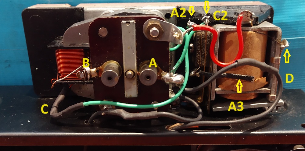
This is the whistle tender with the cover off. The wires have been replaced. Doesn't look too bad. A WS125 Vertical mount whistle.
Power flow
Center track power goes to the brush on the right at A. From the brush on the left to the motor winding. B and then from the motor winding to the ground wire C. The Ground wire C to C2, the connector for the switch. The red wire "grounds" the whistle relay body. The relay coil is grounded to the body at the D arrow. The Relay gets center rail power from A, to the A2 strip connector and that is connected at the bottom to the A3 coil wire. The whistle relay switch when activated makes the motor ground contact on this setup and the motor runs. The coil always has power. It is the DC voltage on the track that causes it to activate, become magnetic and pull up the switch bar on the bottom of the relay making the ground contact.
On some insstallations, 2671W, the relay is mounted to a metal post on the frame. In this case there is no "red" or ground wire to the relay needed. The mount grounds it to the frame. Similar for the early model, metal body whistles. The relay mounted to the metal body grounds the relay.
When the wires to the motor winding get reversed as to which goes to ground vs which goes to the brush, the motor runs backwards and will not whistle as well. Don't switch them. The correct direction when looking from the top of the whistle is CCLW, counter clock wise. CCLW in the picture above.
Whistle Relay
Now after taking it all apart,look at the whistle relay.
 L
L
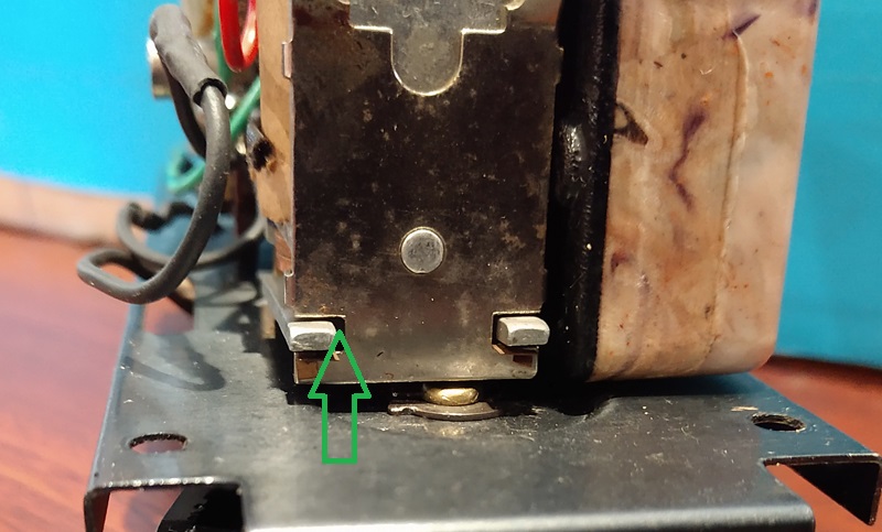
Look at the relay overall. Is there rust or a an oxidize film. This may interfere with the relay working or making good contacts. Green arrow above shows where the plate contacts the body when active. This needs a good electrical contact. I have had to use a small wire brush to clean on the gap where the green arrow is pointing, mostly on the top. To help get a good contact. On the bottom of these tabs there are delicate copper tabs, be very careful.
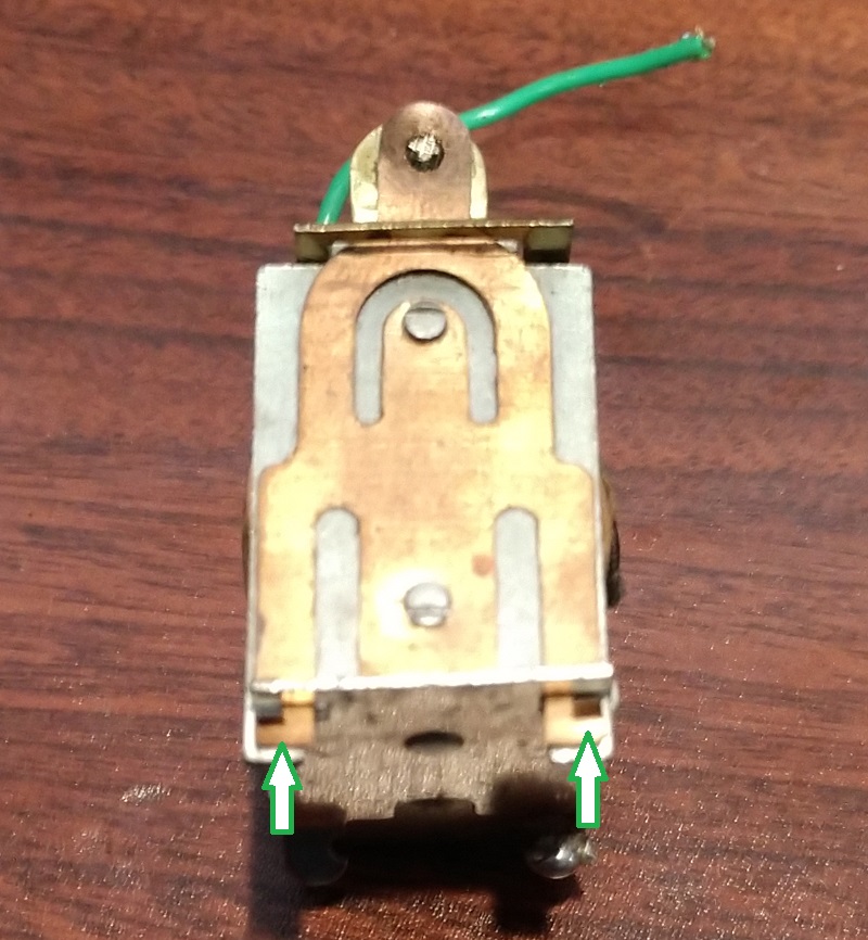
The arrows above show where the small copper tabs are that are attached to the copper plate. If one or both are broken the plate will move sideways and not make a good contact at the "points"
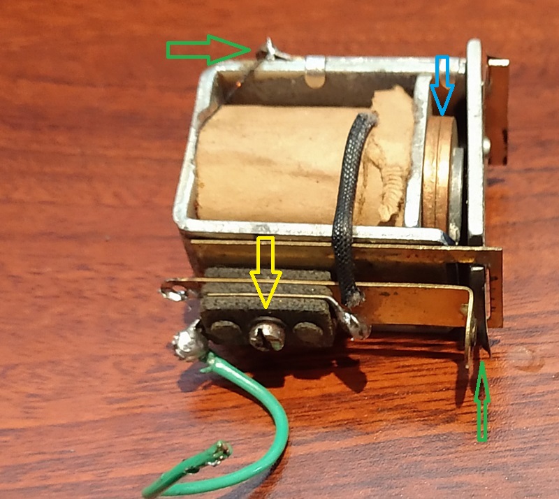
Check the contact points, bottom right green arrow above. I use contact cleaner to make sure it is clean. Manually test to make sure there is a good gap and good contact when closed. You bend the contacts as needed to get the gap correct.
Check the bolt holding the contact assembly. Left Yellow arrow above. The end should NOT go further than flush with the case on the inside. When the end of the bolt protrudes near or touching the coil, the relay may flutter or not work. The insulators may shrink in thickness over time. A washer may need to be added to keep the bolt end from protruding.
Do not get the insulators wet, If they are wet or damp, they will short the power. Usually not enough to flip a breaker, but you can see sparks at times. If they were cleaned and got wet, make sure they are dry for assembly.
The 2 copper disks must be clean, Top Right Blue arrow. Also tight and tight against each other. Usually they are. Clean off any corrosion, dirt or gunk from the disks and the protruding metal post. I have found corrosion build up and dirt reduce performance. The 2 copper disks are what make this coil activate with DC vs. AC from the track.
Check the wiring to the coil. Ground wire should be solid, Top left green arrow above. Make sure connections are good.
Contact Cleaner
The contact switch, bottom right green arrow above, is sensitive to any oil, or dirt. I have often found a spray of contact cleaner on the switch contacts will make the difference between a good contact and a poorly working switch. I also use the contact cleaner on the movable bar. On the pivot to the right of the blue arrow above. Also in the middle to make sure oil and gunk don't cause the bar to stick to the magnetic bar. Be careful with contact cleaner. If it gets on plastic parts it may mark or ruin the plastic. It can remove lettering so be careful with it. Read the warnings on the contact cleaner you choose. I use it outside or in the garage, not in the house.
Soldering the Relay and Field wires
Both the relay coil and the Field coil used wires with an insulation coating. Much like a varnish. Do not scratch these coils. On the ends that are soldered, this varnish needs to be removed for a good solder contact. If not done well at the factory, corrosion and resistance could build in the solder joint. De-soldering the wire, cleaning the end and re-soldering may help the field and relay coils. I would do it on the field coil during cleaning and for the relay coil if it shows signs of not working consistently or well.
Smell the wires on the field coil and armature. If they have a strong burn smell or show spots of discoloration in the wiring, they may have a short and need to be rewound or replaced.
Next the brush plate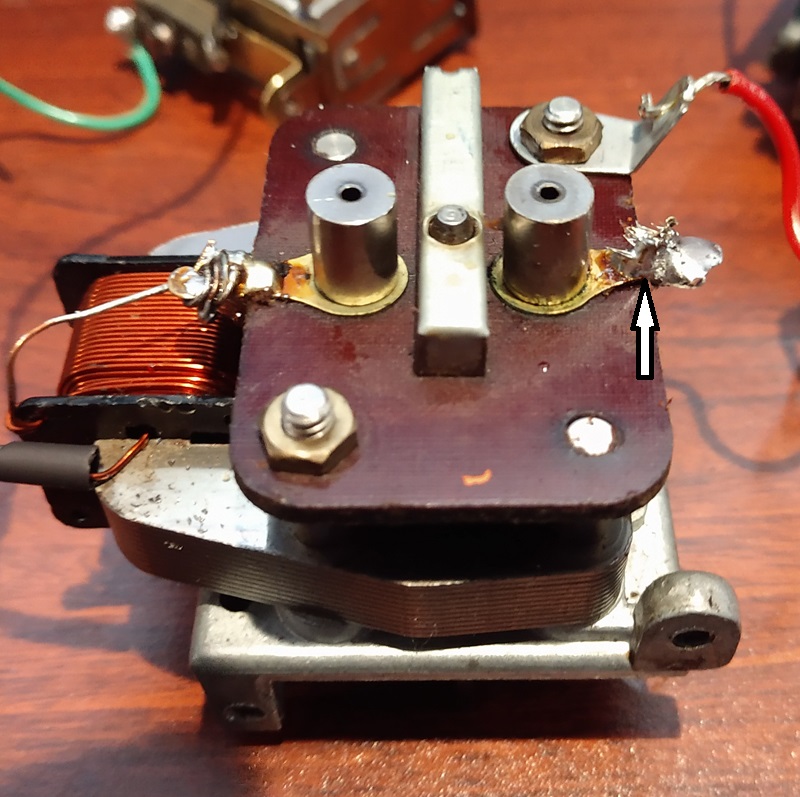
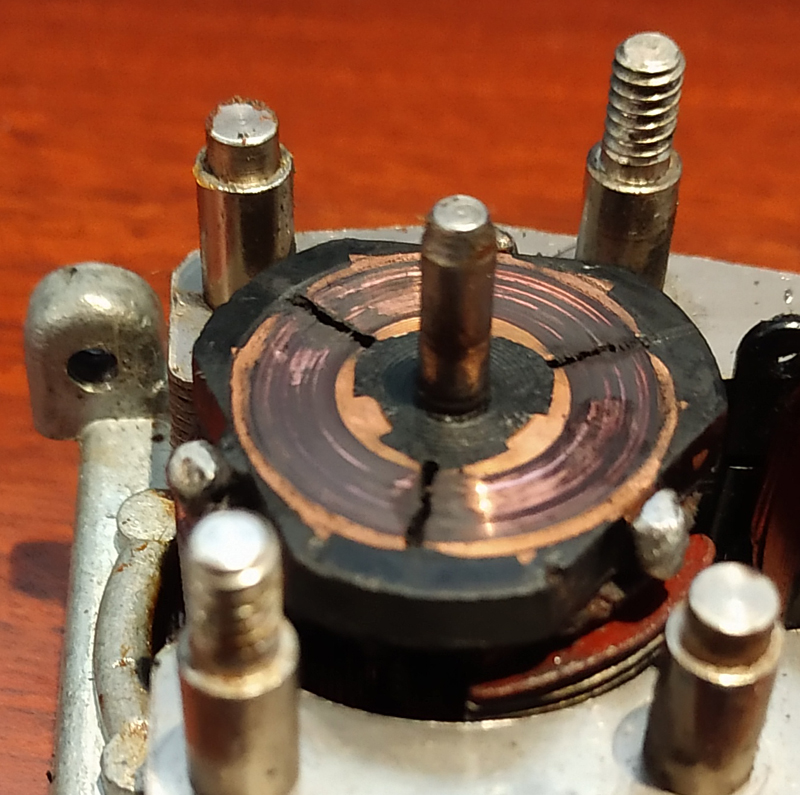
This brush plate looked good initially. Checking the solder tabs, the one on the right moves easily around the brush tower. It may not have a good electrical connection. It may need to be soldered to the brush tower. But taking it off and looking underneath...
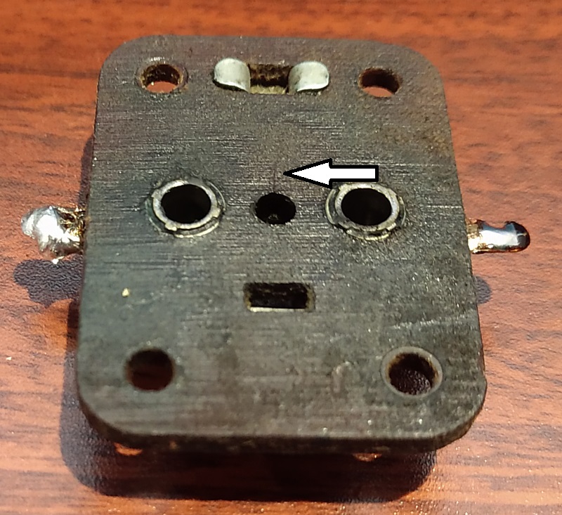
Looking closely at the underside you see a small crack. Unusual in a laminate like this. Maybe not thru, but at least part of the hole for the shaft is now bigger, which leads to wobble and rattle.
My preferred solution.
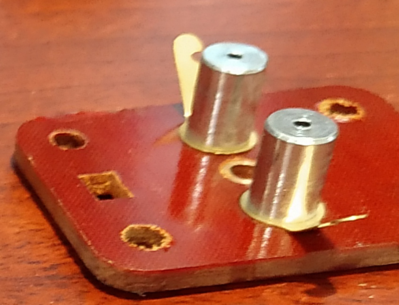
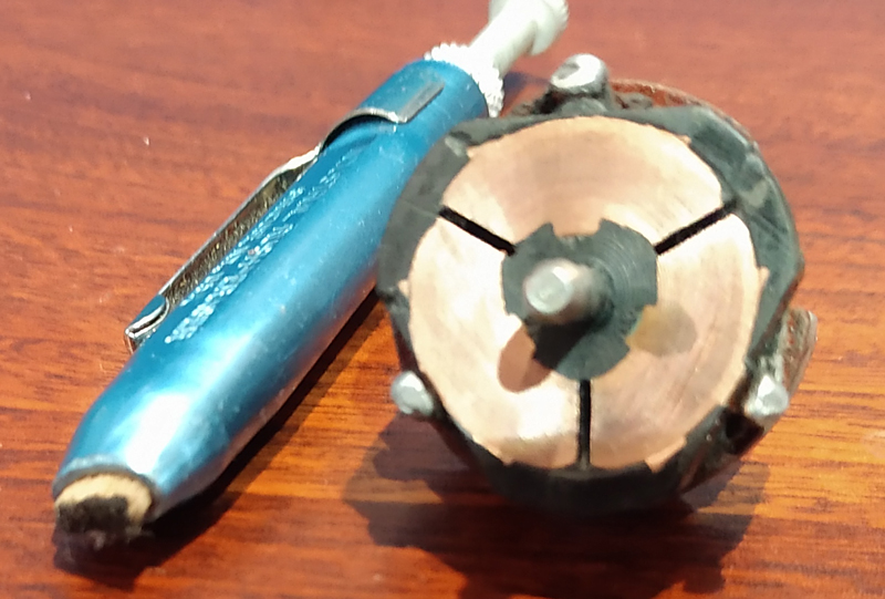
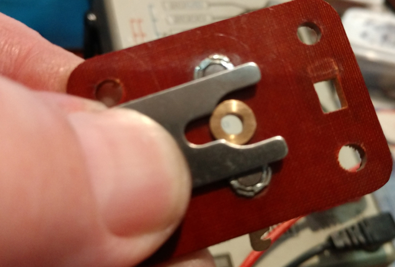
This is a late Postwar whistle brush plate. It has a brass bushing, not just a hole in the fiber board. Why is this better? self oiled. Less wobble-marble sound. Also it touches the shaft in a slightly different location in case there is wear on the shaft. The fiberboard often wears a groove in the shaft that can lead to wobble. Just 1 small drop of good oil is all you need after assembly.

The brush plate on the older WS75/85 whistles do not have a brass bushing option, unless you make one yourself. Amazingly this one still worked well after cleaning the brush towers. In the long run a new replacement may be needed.
Always check that the brushes move freely in the brush towers before re-assembly. This new plate needed new brushes also.
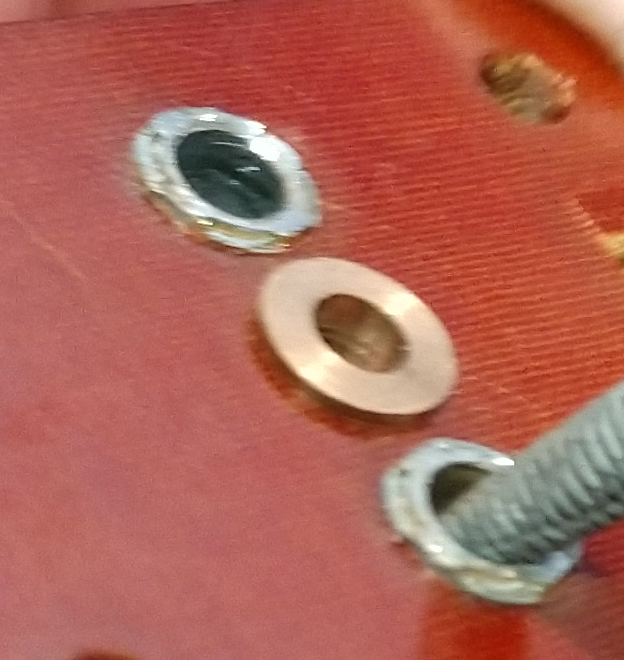
They holes are slightly smaller because of a lip. You may need to remove any edge burs on the brush towers with a new plate. To prevent the brushes from hanging. CAREFULLY remove burs with light pressure. And maybe a finer file than shown hear. File a little and test the brush clearance. It shouldn't take much.
When re-using the brushes and brush plate I use Q-tips and mineral spirits to clean out the inside of the brush towers. A little Mineral Spirits for cleaning the brushes also. Make sure all are wiped clean of the mineral spirits. Mineral spirits also work for the initial cleaning of the armature contact plate.
Brush Springs
The brush springs need to be inspected. Some may have collapsed. While holding the brush plate upside down, install the springs and brushes. The brushes have a small end that fits into the spring. The brushes should extend all the way out of the brush holes, but no more.
If the brushes stay down in the hole and they move freely, The spring has collapsed. You may be able to pull the spring apart and stretch it longer to get the correct tension. Or new springs may be needed. If the spring is collapsed or too short, there is not enough tension to keep good contact with the brushes.
If the spring also extends out of the hole more than 1/8", it may be the wrong spring. I had a whistle that had been serviced and the wrong springs put in. It stuck out 1/2" and was a stiffer spring. The extra pressure on the brushes retarded the spinning of the armature and it would not whistle. Once I put in the correct length springs it whistled well.
On to the armature
This is what it looked like. Not bad, but needs to be cleaned. It had a little oil on it also. I often find oil. When things don't work, some keep adding oil until it wont work at all. I think this one was a just little over oiled, I have seen much worse.
This is the rush eraser I use to clean the contact plates. If there is a lot of gunk, you may need to clean off the end of the eraser before finishing. It took less than 1 minute to get the surface smooth and bright. Multiple light brushes. Make sure the gaps are clean. It should be flat and smooth. If grooved or wavy or just worn thin from use (rare) it may need to be replaced.I test for shorts and continuity. There are 3 contact plates on the armature 1-3. I check between 1 to 2, for connection, 2 to 3 and 3 to 1. All should show a good connection. From any one of the plates to the shaft or metal plates should show no connection, no short. Check the wires for discoloration areas, heavy burned smell. This one looks good. Same for the motor winding. Good connection between each end of the winding, no connection between the winding and the motor housing. Also make sure the gaps between the plates are clean. A toothpick usually works for this.
Take off the fan. It is the only way to get a full inspection.
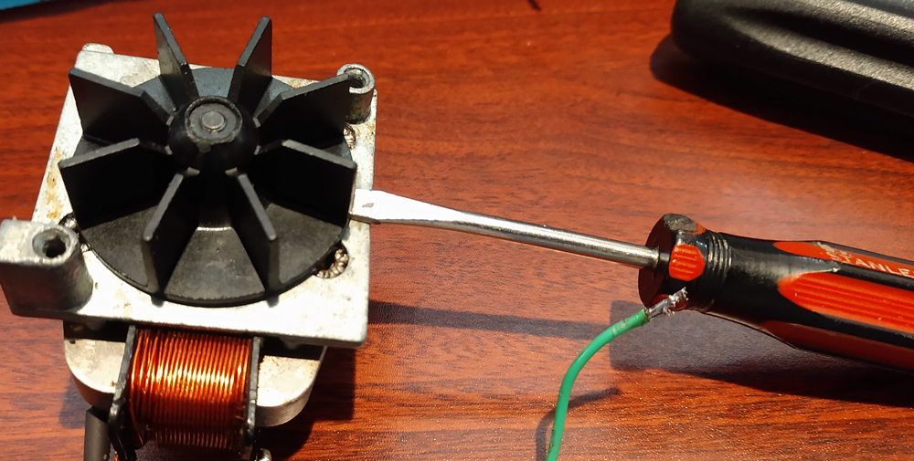
Carefully pry the fan up. A little on one side, A little on the other. DO IT WHERE THE RIBS ARE. If you pry on the flat areas it will most likely break. It will get easy and come off. Notice the shaft has slight ridges that keep the fan from slipping on the shaft when turning.
Once the fan is off, pull up the shaft until is sticks in the bushing. Now if there is enough room do the inspection, cleaning and greasing of the next two steps, you don't have to drive it all the way out of the busing. If the plastic bushing on the shaft shown below is worn, you will need to remove the shaft out of the bushing completely to replace it.
You may need to tap the armature shaft out thru the bottom bushing because of the splines prevent it from pulling through. If the splines are too pronounced, you may need to sand them down a little to get them to go thru the bushing without too much trouble. If it the bushing starts to push out instead of the shaft going through, the splines need to be sanded down. DO NOT TURN the armature while doing this. If possible mark the rotation location and put it in the same way later.
Now look at the motor housing and the bushing in the base.
Look at the brass bushing and clean all the old gunk off and make sure it is smooth on top. If chipped or worn it must be replaced, but usually they are good. When everyone tells you to oil the whistle like crazy, this is the area they are talking about. Does a lot of oil help, not really, except it may loosen old hard oil causing drag. I clean away the old grease. I apply a PTFE based lube on top of the bushing. The base of the motor rides on top of the bushing. When I can find some wear specifications I will post them here.
The older WS75/85 style whistles do not have this bushing between the winding and the impeller. You do not need to pull the impeller. In most cases the whistle housing has been riveted together and disassembly to access the impeller is not recommended. On the WS75/85 the end of the armature shaft rides on a ball bearing inside of a bushing. There are two styles of bushing. Light to medium grade oil is needed for these bushings.

This style is pressed into the cover plate. There is a small ball bearing in the middle. When oiling, you need a small pin to push the bearing up to let the oil penetrate inside. This cover uses press in rivets and does not disassemble well.

This style the bearing is held in with a spring strap. Turn the keeper on the top in this picture 90 degrees to remove the strap.

This shows the bearing ready for oiling. There is a small ball
bearing inside the bearing, don't loose it. Often they are
stuck inside. I use a medium viscosity train oil.
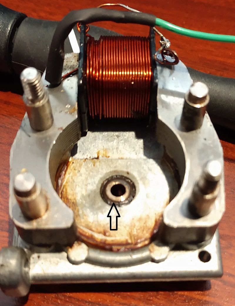
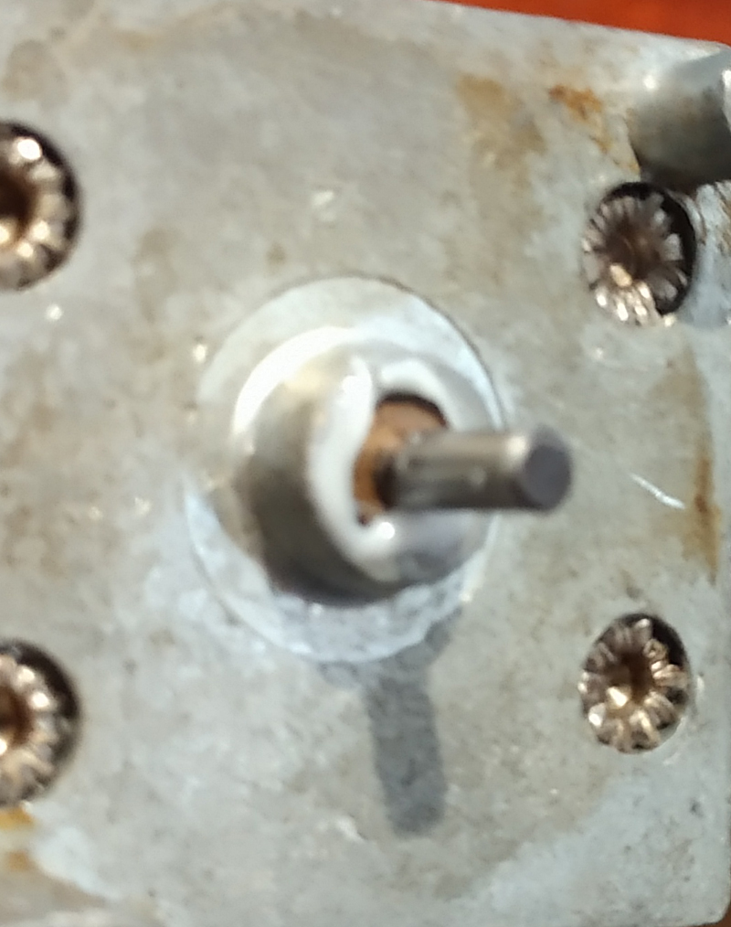
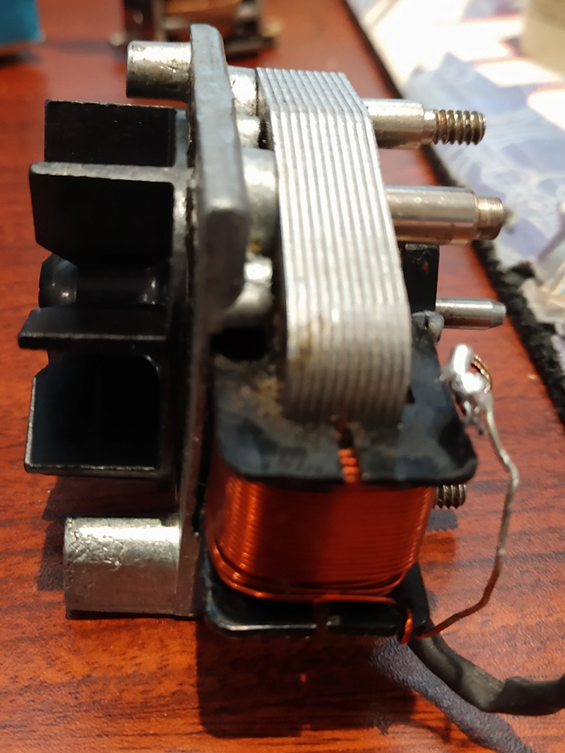
The shaft on this whistle normally runs horizontally, no pressure on the end. The arrow shows the bottom plastic bushing on the motor. It can be replaced if you can find one. Also a good 3D print project. There are also plastic washers that can be used to shim this if worn. In this case it is in good shape, adding a washer is not needed. If worn down a thin Stainless Steel washer could also be used to get the correct spacing back. It needs to stay centered correctly in the motor. Worn and loose, it moves left and right along the shaft. Too tight and it wont spin correctly. To me it is experience. If I find dimensions to measure the wear, I will put it up here.
Balancing WS125/175 armatures
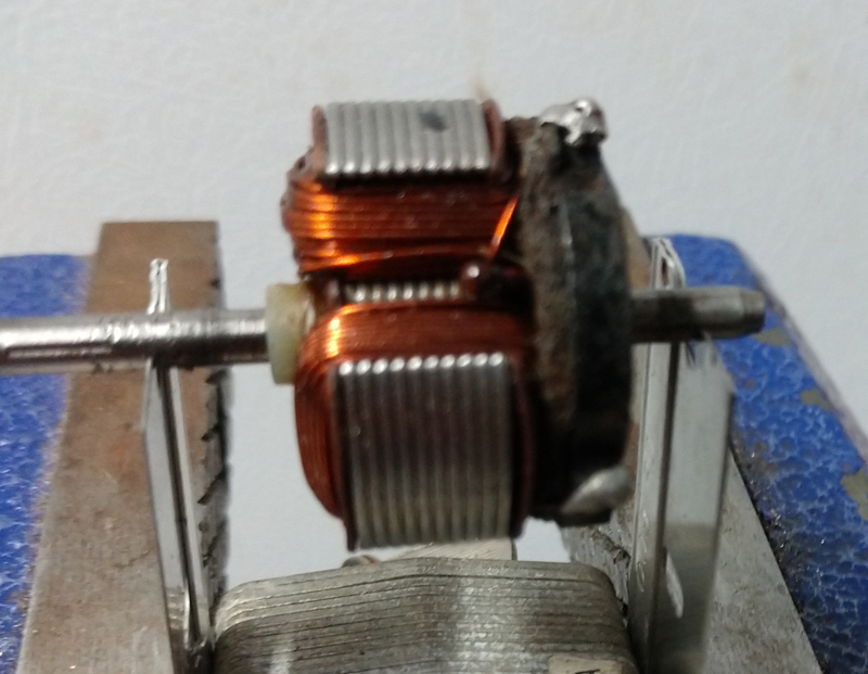
This razor blade setup will not do fine balancing, but will show large balance problems. I am still looking for a good fine balance at home solution. Not generally a problem, but I would like to see how fine balancing effects the results.
Now put the armature back in the motor base.
The motor bushing is level or below the housing on the fan side. It can vary depending on housing. Make sure the housing around the bushing is smooth, this is where the fan will rub. Add a little, plastic friendly light grease. Keep the exposed part of the shaft free of grease. The fan mount doesn't need grease.
Put the fan back on.
It should press on. Don't try to put it in the exact same orientation as before. You want new grooves cut into the plastic as you press it on to hold it well. How far, carefully as far as you can without binding or bottoming out. Make sure it spins freely. If you had to sand the ridges down on the armature shaft, a little dab of hobby glue in the fan shaft should help to keep it from slipping.
Now put the brush plate back on. first test fit the plate without brushes. To make sure nothing binds and the fan/armature spin freely.
This is a handy tool I use to hold the brushes while I fit the brush plate on the motor. You can carefully do it with the plate upside down, but this just saves a lot of time and possible problems. You can even cut a tool out of heavy card stock for this. Or rubber bands you just cut later and so on.
Now the whistle housing.
![]()
If the housing is being re-used with the motor, it should all fit and clear. If the whistle housing is changed you may have to make adjustments. The fan should not drag on the housing. I have seen some that had the fan blades sanded down, or paper gaskets made to raise the motor a little higher when mating to the housing. These were toys and I think a little custom fitting was done now and then.
Check the whistle exit points, both places.
On this whistle box one exit area had a lot of glue over-run that was bumpy and sound was a little off. I filed the angle area back flat, but not too far. I don't know how to tune for sound so I didn't do too much. But it sounds better with a better air flow over the edge.
I usually test the fan/motor alone with jumpers from the track or transformer. Connected to the ground from the winding and to the right side bushing connector. Hook up jumpers and apply power. If all is good you should hear a good whistle. If not, fix it before final soldering.Then hook it all back up and enjoy a whistle not a rattle.
While the Postwar horn relays are durable and often work well, I find they just miss working from time to time for whatever reason. There are good aftermarket electronic horn relays that come with a mechanical relay built in to handle the power. They seem more reliable to me. Some have both AC and DC wires for Postwar and modern fan driven whistles. On a postwar tender the 12v DC could be used to have LED lights turn on with the whistle or some other fun thing. Maybe make someone riding on the tender wave.
Voltage needed to make a whistle work.
Early Metal Body whistles, WS75 and WS85. There is a note in the service manuals stating the WS75 for O27 and The WS85 for O gauge units had the field wound differently. The WS85 operated at 11 volts, while the WS75 would operate at 9v. In general the O27 systems were lighter and needed less voltage to run so the whistle needed to work at lower voltage. Mechanically the units were identical.
Over the years and with various repairs, A WS75 and WS85 could have been switched, so be aware. WS125 is listed as the replacement for the WS75/85
Plastic body whistles. W125/175 show they should start at 4-5 volts, but what voltage they will whistle at is not listed. After repairs they should be run at 12-15 volts, maybe for a few minutes. I have found run in usually needs a minute or less.
WS175, Horizontal mount and WS125 Vertical mount, armature shafts were trued on a lathe before assembly at the factory to guarantee a straight shaft.
Back to Main page.