
Wiring and Repair of the Bell Ringers
Repairing these tenders can be interesting since there are 4 wiring options and previous owners may have modified the tender wiring also. Hopefully what I have learned can help.
These bell ringers do not ring loud. Usually they are not heard well when the engine is running on the track. They can be best heard when power is applied and the engine is in "neutral" or not moving.
There are 4 types of Bell ringing tenders.


Some users have modified the postwar engines and tenders to allow them to go through switches better. To do this they have made the ground plug a "center rail" connection. Prewar tenders may have had a center rail connection added also. Because of this, you need to validate each wire.
The plugs for the locos. Looking from the back of the tender forward. Left, Center, Right is the loco plug.
The correct light bulb must be used in the tenders. If it is too tall or too big of a bulb the shell will not fit. It is a 1449 14V clear bulb for all tenders.
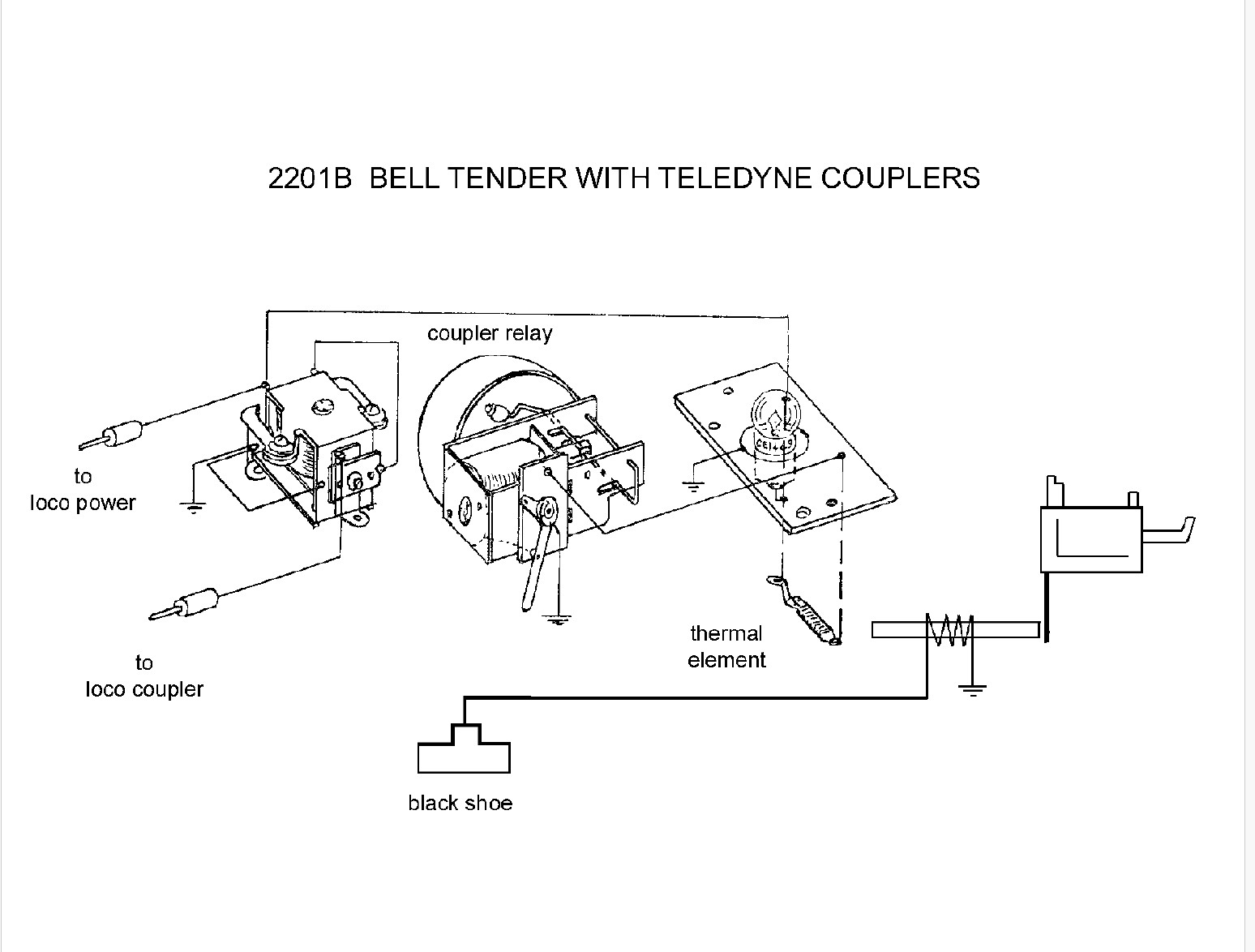
The wiring of a bell ringer can be confusing. That is because the socket for the light bulb is hot or 3rd rail power, not ground as normal. The bulb tip is connected to ground. At the back of the tender is the light board. The thermal switch that controls rate of bell ringing is mounted under this board. The bell connection goes to the relay for the bell. The other switch on the bell assembly similar to an E-unit switch is to ground the relay. If this is off, their is no power flow through the bell assembly. The thermal switch is always connected to ground and is always working to switch power on/off to the bell when there is power.
A view of the thermal switch and 2 of the 3 connection points.
The Ground, outer rail connection is to ground the light bulb.

The hole in the top left of the board is often used to locate the wire that plugs into the engine and connects to the rear coupler and 5th rail shoe for the coupler. On my tender there is also an unused tab at the bell connection. I don't know what it was intended to be used for. It could be an old method for connecting the wire. The bell connection is where the thermal switch is attached on one end. The switch part of the thermal switch is attached to the bottom right rivet.
The ground or outer rail connection also connects to the left bolt as shown with the view from underneath that can be seen below. It also shows the 3rd connection of the thermal switch, the thermal wire ground. It gets the hot or 3rd rail power where it is connected to the contact on the other end.


The plunger returns based on gravity pulling the hammer back down. This means the plunger and hammer must all move very freely. NO OIL on the plunger. To get the plunger out, the sides must be bent out and then bent back in later for re-assembly. Depending on the type, the pivot mechanism may have an end flattened that has to be filed or un-flattened with pliers to get it out when servicing. The Bell Ringer solenoid is essentially an E unit. See the E-unit repair notes for maintaining the coil and plunger.
Wire connection for the Bell assembly.

Replacing a bad thermal switch, Post War example
There are no replacement thermal switches that I have found. Getting one rewound and insulated correctly is time consuming and problematic. Getting it riveted back in is also problematic. I suggest bolting it in if one is replaced.
I found the right automotive flasher can work. This 2 prong, JIN-Y1 super winker 12 v 8-23 watt flasher works well as a replacement for the thermal switch. It was for a motorcycle. I attached it with double back tape. I also taped over the connect to prevent any contact with the shell. Tabs were bent over or cut off. It only works when the solenoid is grounded.

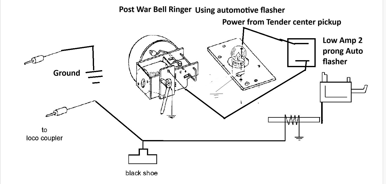
AC works with the flasher especially at the standard running voltages of 10-14v for these small switchers. It tends to switch 20 percent faster than the original. The inside of the flasher and label.


Back to Main page.
Last Update April 21 2025