
These are semi scale 0-6-0 models built a few years before the start of WWII. This was reproduced as the Lionel 6-18000 and many parts inter change, and many do not. That is why some parts are still available. They 6 engines are built to scale, but the couplers and wheel flanges are not. That is why they are called semi scale. The true scale version is the 701/701T that came with scale wheels and couplers. The 701 also only had one wire connection.
These 6 engines are almost identical. There are three differences. First the number on the front of the boiler cover. The second is the remote control option. 227/228 have the Teledyne option for running the couplers. The 230/231 have no remote control option. The 232, and 233 use Magic Electrol control 3rd Plugin on the back of the engine. This is wired to the E-unit. 227 and 228 only have 2 plugins from the tender. The 230/231 have only one wire plugin, the power wire. The third thing is the coupler height on the tenders, 227, 230 and 232 had the lower prewar coupler height and the 228/231/233 had the higher prewar coupler height.
The 230/231 were un-cataloged and sold in un-cataloged sets. A lower cost option.
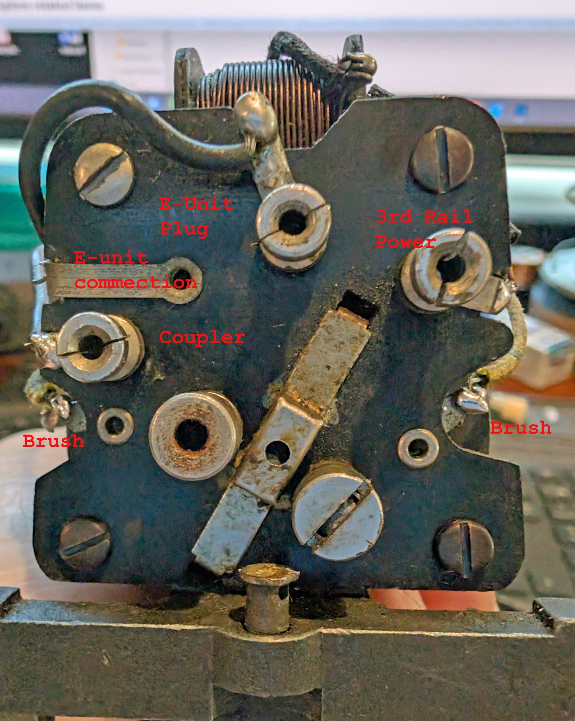
In 1939 the plugins were flush to the back plate. The tall, split collet plug receivers were used in 1940 and 1941.
The back of the 232/233 Wiring connections and plugs noted.
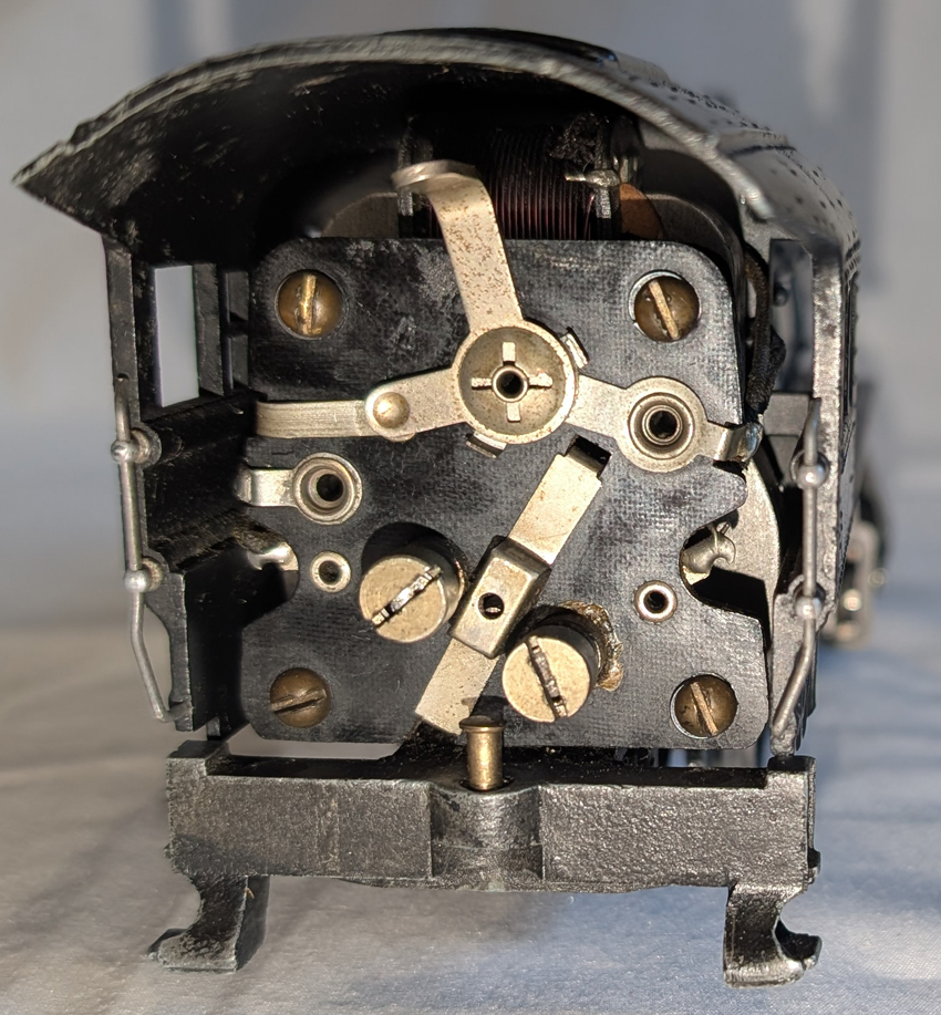
When handling these engine, do not spin the front or back wheels. It puts extra stress on the idler gears and the stock ones are weak. If you need to turn the wheels, turn the center wheels and let the others follow.
This engine uses a motor with a gearing to a drive rod and worm gear assembly that drives the center wheels. Three wheels are geared on the right side and are interconnected by idler gears. A screw is used on the motor gear, not pressed on as they are done now.

There is no smoke unit.
The light bulb screws into the block in the steam chest casting.
The front boiler cover screws are on the inside of the boiler and can only be accessed with the boiler off. The front boiler cover does swing open to access the light bulb.

The E-unit is unique and touchy. Any dirt, rust or wear can limit it's function. See comments below. When cared for and properly adjusted, it can work well.
There are many hand-rail details on this engine. The stanchions are threaded into the boiler and many are blind holes. When a stanchion is broken off, getting the old threaded part of the stanchion out may take work. I had 2 broken off. I got one out, but the other I am still working on. Being careful since I don't want to ruin the boiler. I need some left hand drills most likely.
Repairing my 228 idler pins
In the following I do a lot of cleaning and re-oiling which I don't mention much. I would also suggest detaching the front light wire and the front coupler wire when tearing this engine apart for this kind of repair.
One of the main problems these engines have is the idler pins come loose. This causes wear on the gears and can lead to excessive wear and failure. My 228 had this problem. See the 228-idler video to see how loose mine were.
I found new pins, idler gears and some linkage screws. Thankfully the 6-18000 remake uses the same/similar parts.
First, take the boiler off. 1 screw in the smoke stack and 2 under the front part of the cab. The boiler comes off. Note the light bulb screwed into the casting in the front.

Next remove the linkage screws on the center wheel. There are thin washers under all the linkage screws. Don't loose them. In one case the center linkage had two washers, A thick one and a thin one. Then remove the steam chest by removing the 2 screws that hold the steam chest and front coupler.

Then remove the drive rods. Do not bend the side rod getting it off. Careful turning and positioning of the wheels will allow you to remove the side rods.

Now the steam chest is removed, you can take off the 4 remaining bolts and washers for the side rods. You can only access the front ones with the steam chest off.
Now remove the 4 bolts that hold the top plate over the main worm gear. It also holds the E-unit. There are 2 near the back side (motor side) and 2 near the middle. The middle of the picture shows one in the middle.

Once this cover is off, check the worm gear assembly. The old grease can turn into something like hard plastic. Remove old hard grease and use a good grade modern grease on these worn gear assemblies. If you pull the motor off the frame, you can take the worm gear out, note the position of the brass block on either end. They are directional, meaning they have a specific top and bottom orientation. Mark the tops of the brass blocks on either end with a T or similar before you remove the worm gear from it's box.
You now have access to the valve hanger assembly. There are 2 screws that hold it on the frame. First, remove the long bolt that holds the right small linkage rod to the follower that runs inside the wheel. (bottom in this picture) The right follower will not pull out with the wheel on and stay inside the wheel since the gears surround it. The left side will come out with the assembly since it is not captured by the wheel.

This is the valve hanger and parts once removed. The right follower cannot be taken out until the right front wheel is removed.

Now using a wheel puller remove front and back left side, non-geared, wheels. Check how the right vs left side is indexed. Then carefully remove the geared center wheel on the right side. There is an internal gear on the center axle, do not try to remove this axle. You need a good wheel puller that can grip just the edge, outside the gears. I would not put a wheel puller over the gears.
Remove the front and rear geared wheels with the axles. Check all the geared wheels. If chipped, missing teeth or badly worn, replace the geared wheels. Also check the bearings for wear. If excessive, replace them. 6-18000 bushings and wheels should be the same.
Check the cam lobe of the inside of the front wheels. If they show excessive wear, the front and rear wheels can be reversed. The rear wheels are the same as the front and have an unused, new cam.
Your frame should now look like this. Note the flat spot in the casting for the idler gears. Now you can remove the idler pins. In my case they came out easily.

Looking at the original pins they were pinched of serrated in 2 places, 180 degrees apart. This is one of the problems, the pins did not fit tightly. This let them get loose and wobble.

The new pins are serrated all the way around.

Since my engine had not been run too much with loose pins, the holes were still good enough to hold the new pins tightly and in the right location. I also used a little JB weld to assure they would stay tight. It worked well.
This is the frame with the new pins after cleaning. I have cleaned up to 1/8"-3mm of dirt and grease from behind the wheels after 86+ years.
 I
I
I also installed new Idler gears. The others had started to wear on the inside hole and some on the outside. They help tighten it all back up.
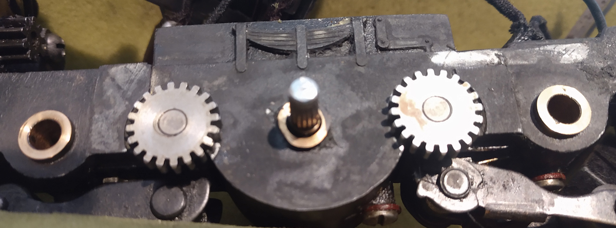
Then re-install the wheels. All 3 wheels on each side need to be aligned together. If not, the linkage will not work or it may bind. Also left to right side need to be indexed 90 degrees from each other to look right. Since all the wheels are gear driven, this is not critical. Indexing is critical when the linkage is driving wheels, such as on the Lionel Berkshires or Hudsons. If not indexed the wheels could bind on starts. I recommend this order.
One of my wheels did not tighten on the axle well. Wear over time most likely. Either a new wheel is needed or some shimming. I found the side of a thin plastic bag draped around the axle worked well. It added about .002"/.05mm. Since it was thin plastic a small knife could remove the excess plastic sticking out. Since then I have also found Vibra-Tite for general use. It is like a lock-tite for shafts. A small drop is all you need and it is strong. Don't get it in the axle bushings.
Wheels re-installed.

Then install the side rods, front and rear nuts and washers only. Note the details go up. They represent the oiling blocks on the steam engine. Then re-install the valve hanger assembly, re-assemble the valve rod and follower with the long side screw. Sorry, the linkage sides got reversed in this picture. Most wont notice.

On my engine there is a power wire from the front pickup to the rear. It is a tight fit where it comes out from under the front of the gear cover. I made a little notch in the valve gear hanger to help with clearance. Then re-install the gear cover with 4 bolts. Note, the wire should go under the front lip of the covers as shown above, Not exposed to the wheels as shown below.

Now the fun part, install the front steam chest. Install the side rods in the steam chest. Make sure they move smoothly. Then put on the steam chest while aligning the valve rods and putting the side rod ends through the slots in the valve hanger.

Now use the 2 bolts to re-install the front coupler and mount the steam chest.
Now reconnect the side rods to the center wheel. There is no washer between the side rods and drive rod. There are 1 or 2 washers on the outside. A thin one and optionally a thicker inner one. I have seen it both ways on these engines.

Reconnect any disconnected wires and test. Then you can put the boiler back on.
The e-unit on these systems is unique. Mine was very touchy and the magnet would not pull up the mechanism from time to time to activate it. This video shows the action of the E-unit. Done manually, but works when the e-unit is energized.
The e-unit must be clean and free of anything that would hang up the dropping action when the coil de-energizes.
Backside of the e-unit, 4 wire attachments

Front side of the E-unit

My fix was to make the lever not drop so far. The bottom of the lever stops on the top of one of the mounting screws. I put a washer under the mounting screw to hold the lever up higher and now it works every time. Amazing what .020"/0.5mm will do .

Some other notes.
The brush tubes on these engines use a screw on cap. If lost or the tube is damaged, I have not found a direct replacement. There are brush tubes made for the Lionel 400E that fit. The nut on the inside of the back plate must be removed to remove the tube. Do no try turning the tube from the outside. If using a 400E brush tube, a slightly longer spring may be needed. Do not use too long of a spring, it adds to drag on the engine.
OGR forum Prewar Steam Switcher discussion on these engines.
Back to Main page.Last Update Sept 17, 2026