Using 3D printed parts
Updated Dec 5 2025
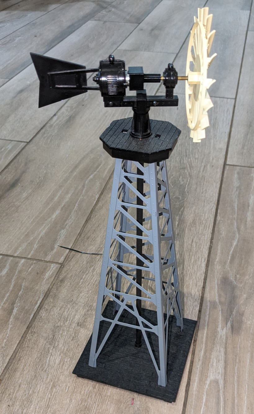
I liked the look of the Lionel 12889 Windmill accessory. The problem was it just wouldn't work well. I checked the experience of others and found that most had it on display without it working. It was unreliable.
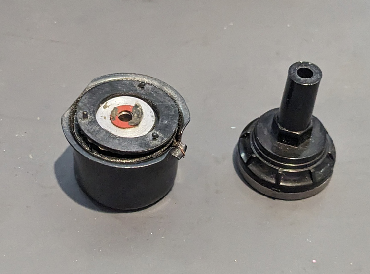
To spin the vanes a traditional coil and rubber footed washer are used. At 60 hrz AC 14v input it should have enough power to spin well. The problem as I saw it was the mass and drag of the overall assembly was too much for it to cycle correctly and spin the vanes consistently. I decided it needed a modern DC motor.
My goal was reliability and relatively slow spinning vane. Along with low power use. .1 amp or less. Why? When you have 1 or 2 accessories pulling 1 amp each, no problem. When you have 10, 20 or 30+ accessories that is a lot of power.
I found the N20 Series gear reduction DC motors that would fit in the space without altering the case of the windmill. They can be purchased currently for under $10. They come in 3,6 or 12 volt versions. With many final gear ranges. I looked for one between 50-100 rpm. I wanted a good spin, but not a fan.
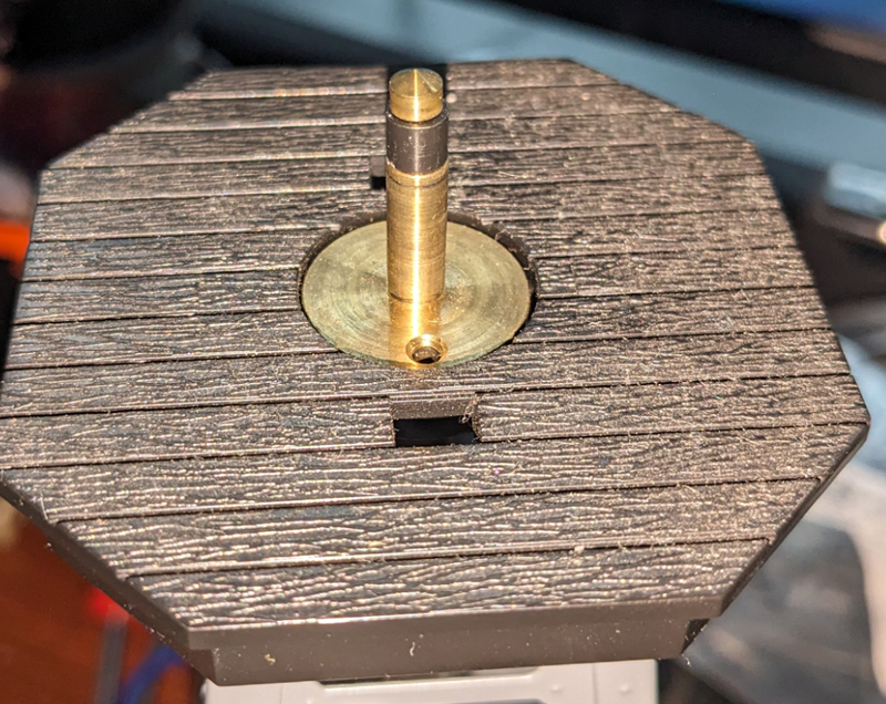
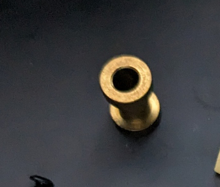
Power is transmitted thru the brass block and
bushing from the 2 shafts in the windmill base. The assembly mounts
on this shaft. After conversion, Supplying the needed DC
voltage to the windmill will now spin the windmill. Just reverse the
wires to reverse direction. A buck convertor can be used to
convert the Lionel 14V AC accessory power to 3, 6 or 12V DC as
needed. Higher voltage causes excess heat.
.
Disassembly
Take the top off and put the base aside. No changes are made to the base.
Pull out the vane with its brass shaft. Put it aside.
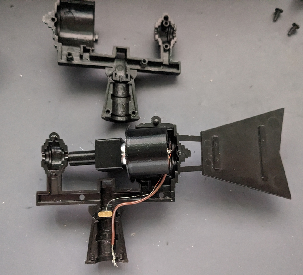
2 Screws are removed and carefully pry apart the top assembly. Careful, a bushing may fall out.
The wires from the coil can be salvaged. Get as much length as you can if you cut them from the coil.
The coil and shaft adapter are no longer needed.
This is the N20 series motor I came up with. 60 RPM at 12V DC. I am going to hook up the windmill to 14VAC by using a Buck Convertor to get the voltage needed. Setting up a Buck Convertor
This has the wire leads with brass block attached that I salvaged from the coil assembly. Now soldered to the motor,
.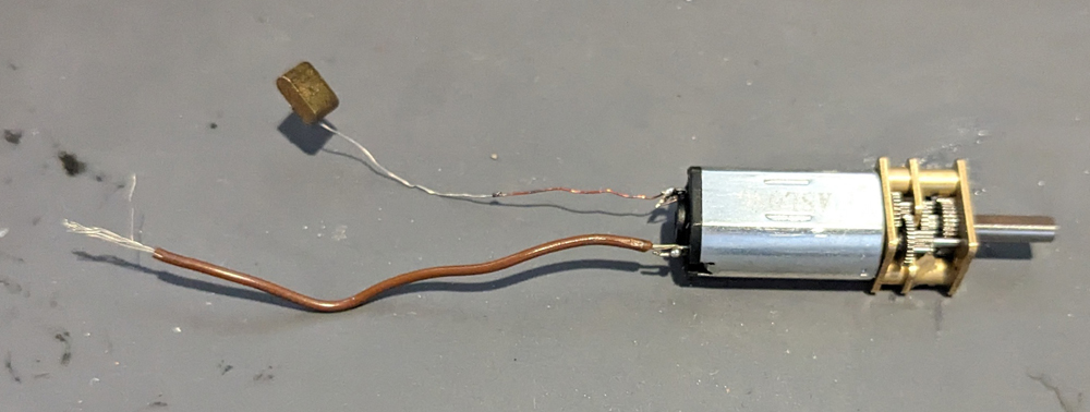
These motor bodies have 12mm/.47" Diameter with 10mm/.39" wide flats. The gear box is 10mm x 12mm to fit in the same box as the motor. The shaft is a 3mm/.12" D shaft with a flat. The length will vary based on the motor and gear box. Over all length of 40mm/1.6" or under will work. This one is 39mm/1.56" long.
I needed 3 pieces that I made with 3D printing to adapt the motor to the windmill.
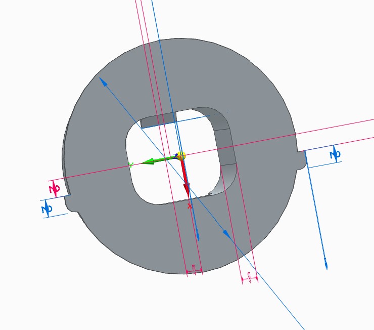
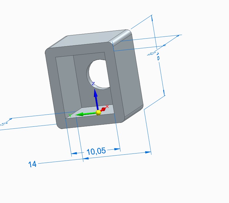
Motor case adapter
Diameter and length matches the coil with a cutout for the motor. A rim was added to match the coil housing. This locates the adapter. 2 tabs were added to keep it from rotating when assembled. A cutout for the wire routing and a stop for the motor depth. The motor presses in with a slight interference.
The adapter from the front. Note the 2 tabs that help orient and prevent it from turning. Holes and slots that have been added to allow some cooling of the motor. When 3D printing I suggest using ASA or better for heat. PETG can be used, but make sure the voltage to the motor is 10 volts or less to keep the motor from heating too much.
Back view showing motor stop and relief for running wires.
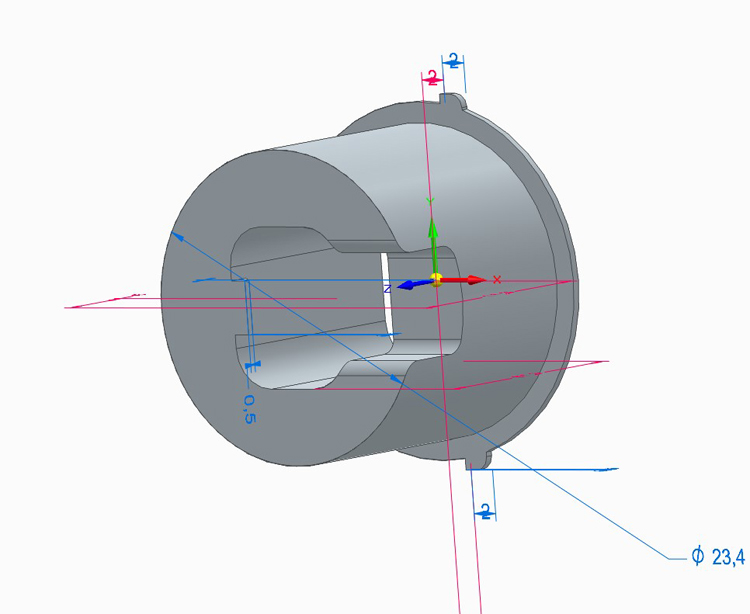
Gear cover. Needed to keep dirt out and grease in. It is a light press fit over the gear box. If it needs to be longer/shorted adjust scaling of that axis as needed.
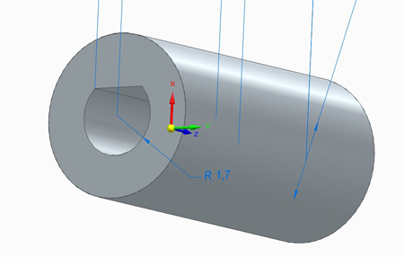
Shaft adapter To adapt the 3mm/.12" D to the 3.16mm/.125" fan shaft. The shaft adapter was sized so final print resulted in the desired fits. Each printer may vary. Hole sizes or scale of the print may need to be adjusted depending on your printer. I have found holes under .2"/5mm do not print to size well with current slicers.
Motor side. Motor side for the D shaft is 9mm/.36" deep, The other side for the Vane shaft is 5mm/.2" deep. The shaft allows adjusting for variations in motor length also.
Assemble the motor and wires in the adapter. Grease gears, add Gear Cover and Shaft Adaper. The D slot of the adapter goes on the motor. Then place in housing. The brown insulated wire is out of place in the picture. It goes under the brass block in a slot in the housing. The brass block fits in a slot.
Put the bushing back in the base in its cutouts. Make sure it contacts the bare ends of the insulated wire. The insulation should not go below the top of this busing, only the bare end.
Carefully assemble the other side and make sure:
The brass vane shaft is now too long, it must be cut shorter to fit. I cut mine to 1.1"/28mm long from the base of the vane, or the length of the visible shaft. Another .3"/7mm sticks into the vane.
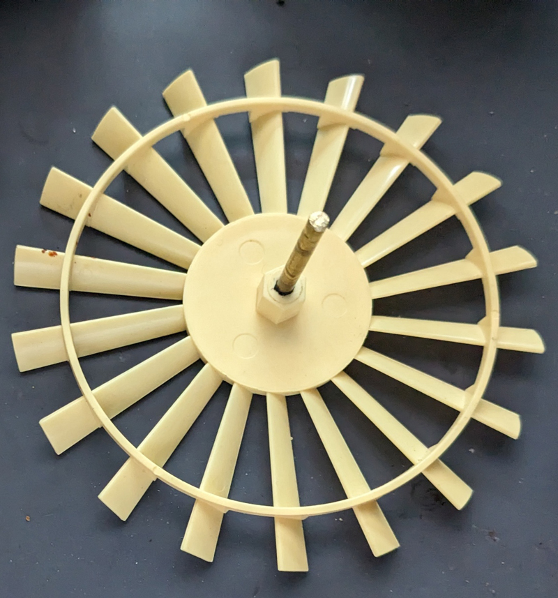
The vane shaft is a light press fit into the shaft adapter.
This is what it looks like assembled. Or look at the picture at the start for the full assembly.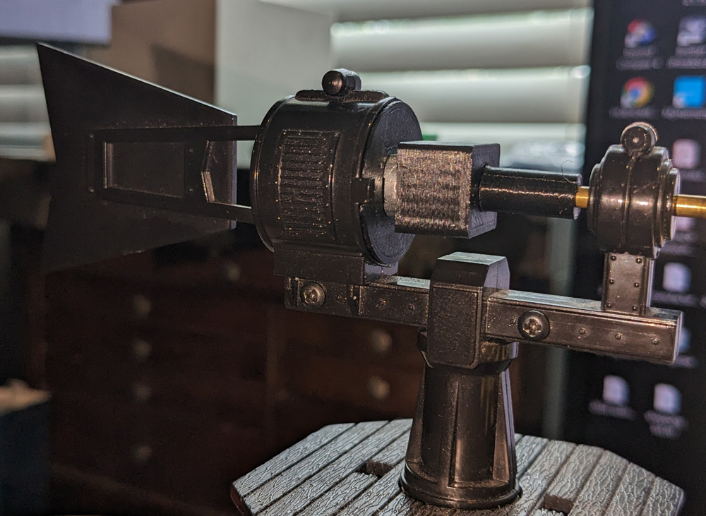
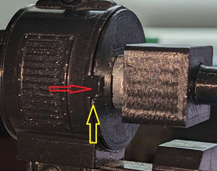
Details of the motor adapter. Red arrow shows the housing clips the ridge fits in. Yellow arrow shows the position of the tabs, under the housing clips.
3D files and instructions .zip
These project .stl and step files I created are also available on the OGR 3D printing Catalog.Back to Main page.
Last Update Dec 5 2025